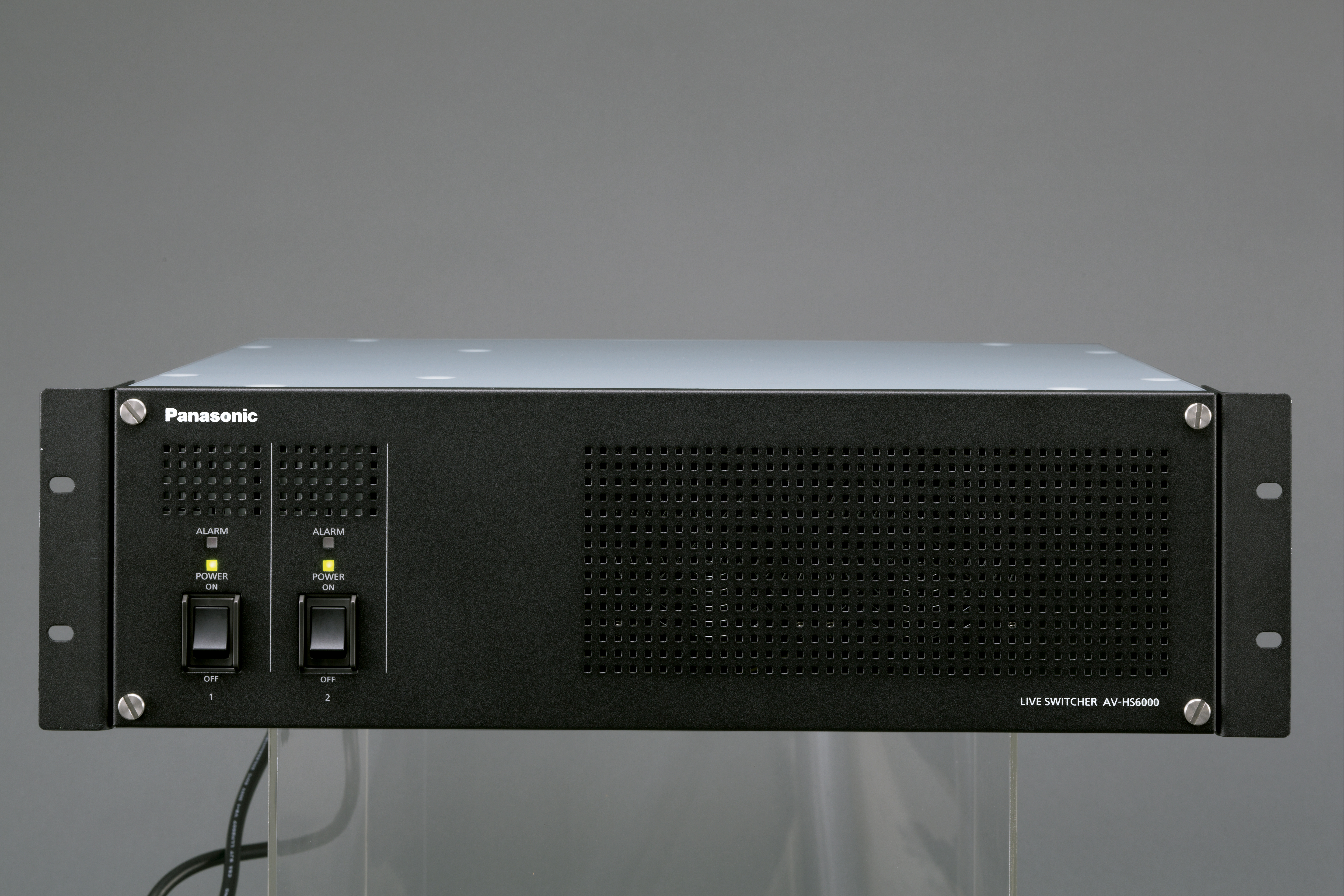
| Mainframe -> Model No. | AV-HS60U2P/E |
|---|
| Mainframe -> General -> Power Supply | AC 100 V to 240 V, 50 Hz/60 Hz
(supports redundant power supply) |
|---|
| Mainframe -> General -> Power Consumption | 110 W |
|---|
| Mainframe -> General -> Operating Temperature | 0 °C to 40 °C (32 °F to 104 °F) |
|---|
| Mainframe -> General -> Operating Humidity | 10 % to 90 % (no condensation) |
|---|
| Mainframe -> General -> Storage Temperature | 0 °C to 40 °C (32 °F to 104 °F) |
|---|
| Mainframe -> General -> Storage Humidity | 10 % to 90 % (no condensation) |
|---|
| Mainframe -> General -> Weight | Approx. 13.5 kg (29.7 lbs.) (excluding accessories) |
|---|
| Mainframe -> General -> Dimensions | W 482 mm x H 399 mm x D 418 mm
(18-31/32 inches x 5-3/16 inches x 16-15/32 inches)
(excluding protrusions) |
|---|
| Mainframe -> Video Terminal -> SDI IN | During Standard mode Standard 32 lines
• Connector: BNC x 32
• SDI IN 27, SDI IN 28, SDI IN 21, SDI IN 32、SDI IN 32 terminals are equipped with up-converters,
• SDI IN 25 to SDI IN 32 terminals are equipped with color correctors.
HD-SDI
SEMPTE 292M (BTQ-004) standard compliant
• 0.8 V [p-p] ± 10 % (75 Ω)
• Automatic equalizer 100 m (328 ft) (when 1.5 Gbps/5C-FB cable is used)
SD-SDI
SEMPTE 259M standard compliant
• 0.8 V [p-p] ± 10 % (75 Ω)
• Automatic equalizer 200 m (656 ft) (when 5C-2V cable is used)
During 3G mode
16 lines
• Connector: BNC x 16 (only the odd numbered terminals can be used)
• The even numbered terminals , .. cannot be used.
• , .. , and terminals are equipped with color correctors
During 4K mode
4K signal x 8 lines
• Connector: BNC x 32 (3G-SDI x 4 SQD/2SI)
• Can use the 4K signal in SQD format and 2SI format
3G-SDI
3G serial digital, SMPTE424M standard compliant
• 0.8 V [p-p] ± 10 % (75 Ω)
• Automatic equalizer 100 m (328 ft) (when 3 Gbps/5C-FB cable is used)
• 3G-SDI Level B
3G-SDI Level A (FS ON) |
|---|
| Mainframe -> Video Terminal -> SDI OUT | During Standard mode
16 lines (2 distributed outputs per line)
• Connectors: BNC x 32
• ME1PGM, ME1PVW, ME1CLN, ME1KEYPVW, ME2PGM, ME2PVW, ME2CLM, ME2KEYPVW, DSKPGM1, DSKPGM2, DSKPVW1, DSKPVW2, DSK1CLN, DSK2CLN, DSK3CLN, DSK4CLN, SEL KEYPVW, MV1 to MV4, and AUX1 to AUX16 can be assigned.
HD-SDI
SMPTE292M (BTQ S-004) standard compliant
• Output level: 0.8 V [p-p] ± 10 %
SD-SDI
SMPTE259M standard compliant
• Output level: 0.8 V [p-p] ± 10 %
During 3G mode
3G-SDI output: 8 lines (2 distribute outputs per line)
HD-SDI output: 2 lines (2 diestbute outputs per line)
• Connector
3G-SDI: BNC x 16 (odd numbered terminals only)
HD-SDI: BNC x 4 ( and terminals only)
• 3G-SDI signal is output from the even numbered terminals.
- No signal is output from the , ... terminals.
- The HD-SDI signal converted to the 1080i format is output from the and terminals. This signal is converted to the 1080i format by decimating the 1080p signal from the and terminals.
• and terminals are equipped with color correctors. The same color corrector setting is also applied to and terminals.
• ME1PGM, ME1PVW, ME1CLN, ME1KEYPVW, ME2PGM, ME2PVW, ME2CLM, DSKPGM1, DSKPGM2, DSKPVW1, DSKPVW2, DSK1CLN, DSK2CLN, SEL KEYPVW, MV1 to MV4, and AUX1 to AUX8 can be assigned.
During 4K mode
4K signal output: 3 lines (2 distribute outputs per line)
2K signal output: 2 lines (2 distribute outputs per line)
• Connector
3G-SDI (for 4K signal): BNC x 24 (terminal number 1 to 12)
3G-SDI (for 2K signal): BNC x 4 (terminal number 13 and 15)
HD-SDI (for 2K signal): BNC x 4 (terminal number 14 and 16)
• The 4K signal is output in SQD format.
• The HD-SDI signal converted to the 1080i format is output from the and |
|---|
| Mainframe -> Video Terminal -> DVI-D IN | 2 lines
Digital RGB: XGA (1024 x 768), WXGA (1280x768), SXGA (1280x1024),
WSXGA+(1680 x 1050), UXGA (1600 x 1200), WUXGA (1920 x 1200)
Vertical frequency: 60 Hz
Video format inputs: 1080/59.94p, 1080/50p, 1080/59.94i, 1080/50i, 720/59.94p, 720/50p
• Connectors: DVI-D x 2
• The terminals do not support HDCP.
• The DVI-I connector cable cannot be used.
• For the DVI-D connector cable, use a cable with a length of up to 5 m. (16.4 ft)
• / terminals cannot be used during 3G mode and 4K mode |
|---|
| Mainframe -> Video Terminal -> Video Format | SD: 480/59.94i, 576/50i
HD: 1080/59.94i, 1080/50i, 720/59.94p, 720/50p, 1080/24PsF, 1080/23.98PsF, 1080/25PsF, 1080/29.97PsF,
3G: 1080/59.94p, 1080/50p
4K: 2160/59.94p, 2160/50p (SQD) |
|---|
| Mainframe -> Video Terminal -> Signal Processing | [Y:PB:PR] 4:2:2 10 bit
[R:G:B] 4:4:4 8 bit |
|---|
| Mainframe -> Video Terminal -> ME Number | 2 ME |
|---|
| Mainframe -> Synchronous Terminal -> REF Terminal | • Connectors: BNC
• Same field frequencies as those of the system formats supported
In Genlock mode: Black burst or Tri-level Sync input signals (with loop-through)
• If the loop-through output is not used, provide a 75 Ω termination
• In the 1080/24PsF and1080/23.98PsF formats, only Genlock mode supported
• In the 1080/23.98PsF format, black burst signals with10 Field ID (SMPTE318M standard compliant) or Try-level with 10 Sync signals supported
• In the 1080/24PsF format, Tri-level Sync signals supported
In internal sync mode: Black burst output signal x 2 |
|---|
| Mainframe -> Synchronous Terminal -> LTC IN Terminal | This is the LTC (linear time code) input terminal.
• Connector: BNC
• Impedance: 1 kΩ
• Level: 1 to 2 V [p-p] |
|---|
| Mainframe -> Synchronous Terminal -> Video Delay Time | During Standard mode
1 line (H): When the frame synchronizer is set to "Off" and the up-converter is set to "Off"
2 field (V): When the frame synchronizer is set to "On" and the up-converter is set to "On"
• When the signals have passed through PinP, DVE, MultiView, down-converter,
or DVI-IN, a maximum delay of 1 frame is applied in each case.
During 3G mode
2 line (H) When the frame synchronizer is set to "Off"
2 frame (V) When the frame synchronizer is set to "On"
• Maximum of 2 frame delay is added to each when passed through PinP, DVE, or MultiVIew. |
|---|
| Mainframe -> Control Terminal -> LAN Terminal | Compatible with 100Base-TX and AUTO-MDIX (For IP control)
• Connection cable: LAN cable (CAT5e), max. 100 m (328 ft), STP (Shielded Twisted Pair) cable recommended
• Connector: RJ-45 |
|---|
| Mainframe -> Control Terminal -> PANEL Terminal | Compatible with 100BASE-TX and AUTO-MDIX (For Control Panel AV-HS60C2/AV-HS60C4 connection)
• Connection cable (supplied with AV-HS60C2/AV-HS60C4): LAN cable (CAT5e), straight cable, STP (Shielded Twisted Pair), 10 m (32.8 ft)
• Connector: RJ-45 |
|---|
| Mainframe -> Control Terminal -> COM1 (M) / COM2(M) / COM3 (M) Terminals | RS-422 Control Terminal
For master connection for controlling external devices
• Connector: D-sub 9-pin (female) x 3, inch screw |
|---|
| Mainframe -> Control Terminal -> COM4 (M/S) Terminal | RS-422 Control Terminal
For master/slave connection for controlling external devices
• Connector: D-sub 9-pin (female), inch screw
• Switchable between master connection and slave connection via menu |
|---|
| Mainframe -> Control Terminal -> GPI IN Terminal | GPI IN: 18 inputs, general-purpose, photocoupler sensing ALARM OUT: 1 output, open collector output (negative logic)
• Connector: D-sub 25-pin (female), inch screw |
|---|
| Mainframe -> Control Terminal -> GPI OUT1 / GPI OUT2 terminal | GPI OUT: 48 outputs, selected from general purpose, tally
Open collector output
• Connector: D-sub 25-pin (female) x 2, inch screw |
|---|
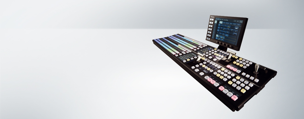
| Control Panel -> Model No. | AV-HS60C2P/E, AV-HS60C4P/E |
|---|
| Control Panel -> General -> Power Supply | AC 100 V to 240 V, 50 Hz/60 Hz
(supports redundant power supply) |
|---|
| Control Panel -> General -> Power Consumption | 40 W |
|---|
| Control Panel -> General -> Operating Temperature | 0 °C to 40 °C (32 °F to 104 °F) |
|---|
| Control Panel -> General -> Operating Humidity | 10 % to 90 % (no condensation) |
|---|
| Control Panel -> General -> Storage Temperature | 0 °C to 40 °C (32 °F to 104 °F) |
|---|
| Control Panel -> General -> Storage Humidity | 10 % to 90 % (no condensation) |
|---|
| Control Panel -> General -> Weight | AV-HS60C2P/E: Approx. 13.9 kg (30.6 lbs.) (excluding accessories)
AV-HS60C4P/E: Approx. 15.0 kg (33.0 lbs.) (excluding accessories) |
|---|
| Control Panel -> General -> Dimensions | AV-HS60C2P/E:
W 980 mm x H 153.4 mm x D 267 mm
(38-19/32 inches x 6-1/32 inches x 10-1/2 inches) (excluding protrusions)
AV-HS60C4P/E:
656 mm×160 mm×400 mm
(25‑53/64 inches×6‑19/64 inches×15‑3/4 inches) (excluding protrusions) |
|---|
| Control Panel -> Control Terminal -> Mainframe Terminal | Compatible with 100Base-TX and AUTO-MDIX (For Mainframe AV-HS60U2 connection)
Connection cable (supplied with AV-HS60C2): LAN cable (CAT5e),
Straight cable, STP (Shielded Twisted Pair), 10 m (32.8 ft)
• Connector: RJ-45
When connected to the terminal, no video will be displayed on the Menu Panel AV-HS60C3G. |
|---|
| Control Panel -> Control Terminal -> MENU PANEL Terminal | Used only for the Menu Panel AV-HS60C3G
• Connector: DVI-D
• Cannot be connected to DVI-D monitor.
• Cannot be used concurrently with a DVI-D monitor connected to the terminal. Select with the display selector switch. |
|---|
| Control Panel -> Control Terminal -> DVI-D Terminal | Used for displaying menus to the DVI monitor
• Connector: DVI-D
• Monitor resolution: 1366 x 768 compatible monitor
• Cannot be used concurrently with the <MENU PANEL> terminal. Select with the display selector switch. |
|---|
| Control Panel -> Control Terminal -> USB Terminal | For DVI monitor menu operation
• Connector: USB (type A, female)
• Cannot be used for the Menu Panel AV-HS60C3G. |
|---|
| Control Panel -> Control Terminal -> Display Selector Switch | Switch for selecting <MENU PANEL> terminal or <DVI-D> terminal |
|---|
| Control Panel -> Control Terminal -> COM1 (M) Terminal | RS-422 Control Terminal
For master connection for controlling external devices
• Connector: D-sub 9-pin (female), inch screw |
|---|
| Control Panel -> Control Terminal -> COM2 (RS-232) Terminal | RS-232 Control Terminal
For external device control connections
• Connector: D-sub 9-pin (male), inch screw |
|---|
| Control Panel -> Control Terminal -> GPI I/O Terminal | GPI IN: 8 inputs, general-purpose, photocoupler sensing
ALARM OUT: 1 output, open collector output (negative logic)
GPI OUT: 10 outputs, selected from general purpose, tally
Open collector output
• Connector: D-sub 25-pin (female), inch screw |
|---|
| Control Panel -> Control Terminal -> ME Number | 2 ME |
|---|
| Menu Panel -> Model No. | AV-HS60C3G |
|---|
| Menu Panel -> General -> Power Supply | DC 12 V/0.54 A
(Supplied from AV-HS60C2/AV-HS60C4 using the supplied cable) |
|---|
| Menu Panel -> General -> Power Consumption | 6.48 W |
|---|
| Menu Panel -> General -> Ambient Operating Temperature | 0 °C to 40 °C (32 °F to 104 °F) |
|---|
| Menu Panel -> General -> Ambient Operating Humidity | 10 % to 90 % (no condensation) |
|---|
| Menu Panel -> General -> Storage Temperature | 0 °C to 40 °C (32 °F to 104 °F) |
|---|
| Menu Panel -> General -> Storage Humidity | 10 % to 90 % (no condensation) |
|---|
| Menu Panel -> General -> Weight | Approx. 1.7 kg (3.7 lbs.) (excluding accessories) |
|---|
| Menu Panel -> General -> Dimensions | W 290 mm x H 177 mm x D 46.1 mm
(11-13/32 inches x 6-31/32 inches x 1-13/16 inches)
(excluding protrusions)
4RU |
|---|
| Menu Panel -> Control Terminal -> Control Panel Terminal | Used only for the Control Panel AV-HS60C2/AV-HS60C4
• Connectors: DVI-D
• Because an independent signal format is used, DVI-D source cannot be displayed.
• Cannot be used concurrently with a DVI-D monitor connected to the terminal of the Control Panel
AV-HS60C2/AV-HS60C4. Set the display selector switch of the Control Panel AV-HS60C2/AV-HS60C4 to the <MENU PANEL> terminal side. |
|---|
| Storage Module -> Model No. | AV-HS60D1G |
|---|
| Storage Module -> General -> Weight | Approx. 7.0 g (0.3 oz.) |
|---|
| Storage Module -> General -> Dimensions | H 29.85 mm x W 4.0 mm x D 50.8 mm
(1-3/16 inches x 5/32 inches x 2 inches) |
|---|


Partager la page
Share this link via:
Twitter
LinkedIn
Xing
Facebook
Or copy link: